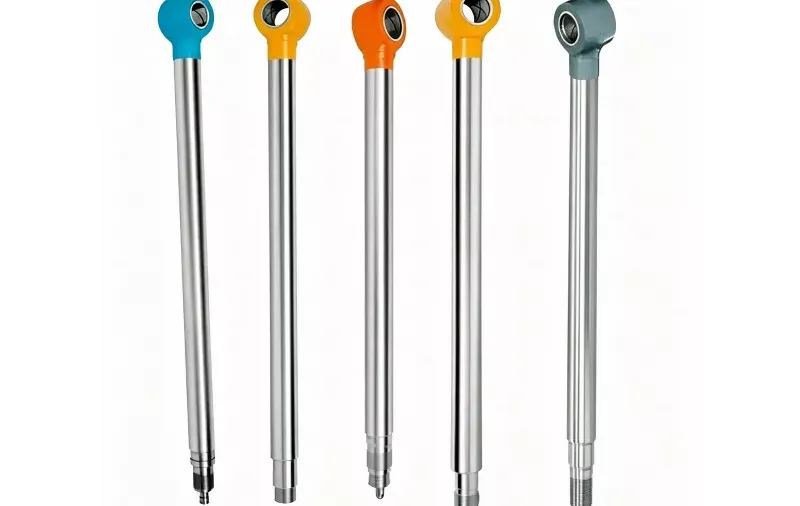
· Engineering Team · Hydraulic Cylinders · 5 min read
Anatomy of a Hydraulic Cylinder: Parts, Materials & Functions
Cylinder barrel, head, piston, rod, seals, base, mounts, cushions, ports, and guide bushings/wear rings—materials, features, and roles in a single comparison table plus detailed breakdowns.
Hydraulic cylinders are workhorses in manufacturing and mobile equipment. They convert fluid power into linear force for mining, pressing, lifting, and countless heavy-duty tasks. High performance starts with how each component is built and how those parts work together.
What makes that possible? Every cylinder is an assembly of barrel, head, piston, rod, seals, mounts, and ports—each chosen for strength, sealing, and service life. Understanding that composition helps you specify replacements, troubleshoot leaks, and match cylinders to your application.
This guide explains how hydraulic cylinders are composed, with a quick-reference comparison up front and detailed notes on each major part.
Hydraulic cylinder parts at a glance
Before diving into individual components, use the table below to compare materials, features, and functions across the main parts of a typical double-acting cylinder.
| Part Name | Composition | Key Features | Function |
|---|---|---|---|
| Cylinder Barrel | Seamless DOM steel or cold-drawn carbon steel | Honed or SRB (skived & roller burnished) inner finish; high yield strength | Houses the piston; holds fluid pressure; provides structural framework |
| Cylinder Head | Ductile iron, high-strength steel, or cast iron | Houses rod seals, wiper, and bearings; corrosion-resistant coating | Seals one end of the barrel; supports piston rod; prevents external leakage |
| Piston Rod | Hard chrome-plated carbon steel or stainless steel | Micro-finish polish, corrosion-resistant, high tensile strength | Transfers hydraulic force; extends and retracts to provide motion |
| Piston | Ductile iron (QT450/QT500) or forged carbon steel | Precision-machined seal grooves; wear-resistant guidance | Separates pressure chambers; creates differential pressure |
| Seals and O-rings | Polyurethane (PU), Nitrile rubber (NBR), or PTFE | Leak prevention; durable under dynamic pressure and heat | Prevents fluid leakage; maintains pressure |
| Cylinder Base | Forged steel or heavy steel plate | Supports mounting; withstands full structural pressure | Closes the other end of the cylinder; provides mounting points |
| Mounting Accessories | Steel (clevis, trunnion, flange options) | Enables various mounting configurations | Facilitates installation in different orientations |
| Cushioning Mechanism | Steel cushion plungers with adjustable throttle valves | Damps end-of-stroke velocity to prevent mechanical impact | Dampens end-of-stroke motion; prevents damage from sudden stops |
| Ports and Connectors | Carbon steel, stainless steel, or brass | Withstands high pressure and pulse vibration | Allows hydraulic fluid to enter and exit the cylinder |
| Guide Bushings & Wear Rings | Bronze bushings; PTFE or composite wear rings | High load-bearing capacity; reduced friction for rod alignment | Supports and aligns the piston rod; prevents metal-to-metal contact |
Hydraulic cylinder parts and their composition
Hydraulic cylinders rely on multiple components working in sync. The sections below expand on each row in the table—material choices, construction details, and why each part matters in the field.
Cylinder barrel (tube)
The cylinder barrel is the main body of the actuator. It shelters the piston, contains the hydraulic fluid, and defines bore diameter and stroke envelope.
Typical barrel materials include:
- Seamless DOM (Drawn Over Mandrel) steel
- Cold-drawn carbon steel
An inner honed or SRB (skived & roller burnished) surface ensures low friction, smooth seal travel, and long seal life under high cyclic pressure.
Cylinder head
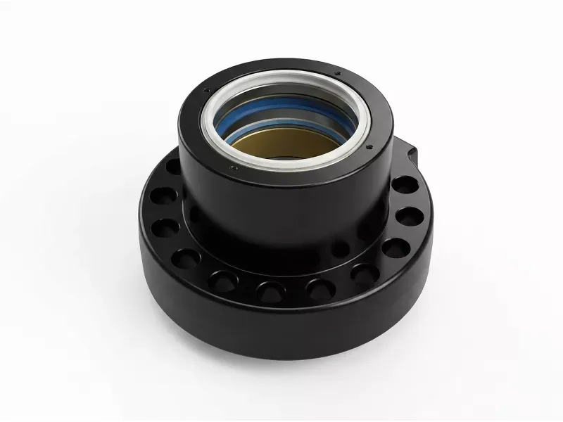
The cylinder head closes one end of the barrel. It provides structural support for the rod, houses rod seals, wiper seals, and bearings, and is the primary barrier against external leakage at the rod exit.
Common head materials:
- Ductile iron
- High-strength steel
- Cast iron
Corrosion-resistant coatings or compatible seal materials are often used on wetted or exposed surfaces.
Piston rod
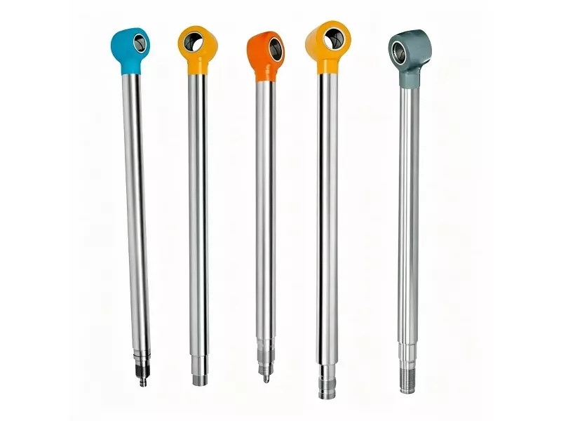
The piston rod connects the piston to the machine linkage and transmits force in extend and retract strokes. Surface finish and hardness directly affect seal wear and rod life.
Rod materials typically include:
- High-carbon steel (hard chrome-plated)
- Stainless steel (corrosive environments)
Chrome plating (or equivalent hard-facing) provides a micro-smooth surface, improves wear resistance, and prevents rust where the rod passes through the head.
Piston
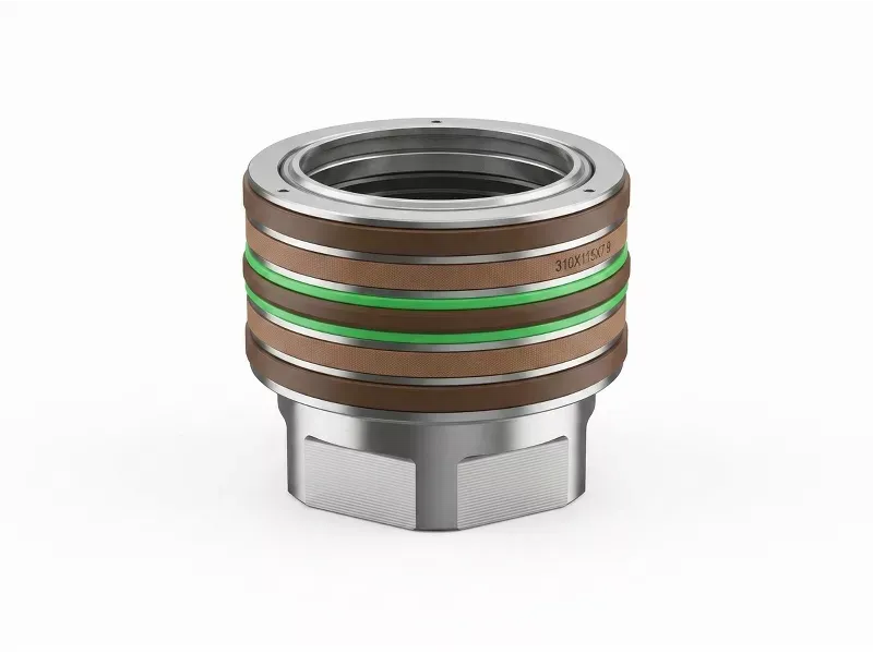
The piston divides the barrel into pressure chambers. Differential pressure across the piston generates extend and retract force on the rod.
Piston construction often uses:
- Ductile iron (e.g., QT450/QT500)
- Forged carbon steel
Piston seals (cup, O-ring, or composite stacks) separate high- and low-pressure sides and must match fluid, temperature, and duty cycle.
Seals and O-rings
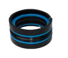
Seals and O-rings contain fluid and maintain system pressure. Rod seals, buffer seals, wiper seals, piston seals, and static O-rings at ports and end caps are common failure points when material or groove design is wrong for the service.
Seal materials include:
- Polyurethane (PU)
- Nitrile rubber (NBR)
- PTFE (Teflon)
Selection depends on hydraulic fluid type, temperature, pressure peaks, and speed.
Cylinder base
The base end (cap end) closes the opposite end of the barrel from the head. It may include porting, cushioning pockets, and mounting interfaces (flange, trunnion, or threaded tie-rod connection).
Base materials:
- Forged steel
- Heavy steel plate
Alloy choices vary with pressure rating, mount style, and corrosion exposure.
Mounting accessories
Mounting hardware determines how the cylinder is attached to the machine frame or linkage. Orientation and load path affect bearing life and side-load on the rod.
Common mount types and materials:
- Clevis mounts — steel
- Trunnion mounts — hardened steel
- Flanges — cast or forged steel
Correct mount selection reduces misalignment, rod buckling risk, and premature seal wear.
Cushioning parts
At end of stroke, high inertia loads can cause impact and vibration. Cushioning mechanisms (using cushion plungers and throttle valves) throttle fluid discharge in the last portion of travel to decelerate the load smoothly.
Cushion components are often made from:
- Hardened steel
- Brass
Cushions protect the cylinder, mounts, and machine structure from shock loads.
Ports and connectors
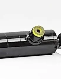
Ports and connectors route fluid into and out of the barrel. They must withstand operating pressure, pulse, and vibration without cracking or loosening.
Typical port materials:
- Carbon steel
- Stainless steel
- Brass
Proper port size, orientation, and adapter selection minimize flow restriction and heat rise.
Guide bushings and wear rings
Guide bushings and wear rings support and align the piston rod and piston, especially on long strokes or when side loads are present. They prevent metal-to-metal contact and reduce friction at the head and piston assembly.
Common materials:
- Bronze (for heavy-duty bushings)
- PTFE and composite resins (for low-friction wear rings)
Conclusion
Understanding how hydraulic cylinders are composed supports safer operation, longer service life, and smarter rebuild or replacement decisions. Material quality, seal compatibility, and correct mounting are as important as bore and stroke on the data sheet.
When specifying new or custom cylinders—tie-rod, welded, or telescopic—contact Hydraulicsmfg with bore, stroke, pressure, port, and mount details for an OEM/ODM quote and pressure-test documentation.